
Click to open expanded view

Product features
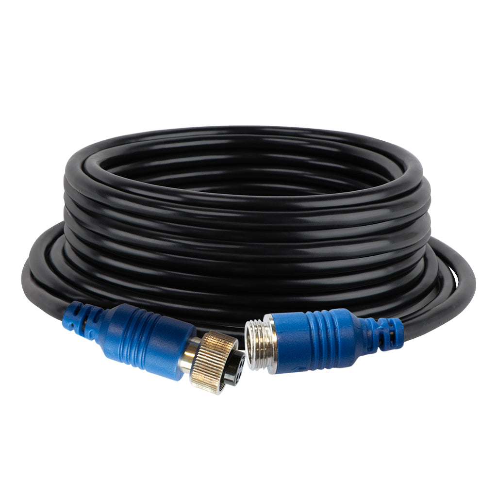
AXIS HDC10M-4P - 10 Metre 4-Pin Extension Lead
High-grade low-loss camera extension cable featuring 10-metre length, industry-standard 4-pin male to female configuration, blue aviation connectors, weatherproof construction, shielded design for signal integrity, gold-plated contacts, threaded locking coupling nuts, and compatibility with universal standard 4-pin backup cameras and monitor systems in commercial vehicles, caravans, and 4WD applications.
Product Overview
The AXIS HDC10M-4P 10-metre HD camera extension cable connects to industry standard 4-pin cameras. This extension lead enables camera placement at greater distances from monitors or recording equipment overcoming cable length limitations of standard factory camera cables. High-grade low-loss cable construction maintains video signal quality over 10-metre distance preventing degradation, interference, or voltage drop common with inferior extension cables. Industry-standard 4-pin configuration ensures compatibility with universal pinout cameras and monitors from various manufacturers eliminating proprietary connector compatibility issues. The male-to-female design features 4-pin male connector on one end plugging into camera female output connector or monitor female input, with 4-pin female connector on opposite end accepting male plugs from existing camera cables or monitor input cables. Blue connector housings provide visual identification distinguishing this extension cable from other vehicle wiring simplifying installation and future troubleshooting. Aviation-grade 4-pin connectors deliver IP67 weatherproof sealing when properly connected protecting electrical connections from moisture ingress, dust contamination, and corrosive environmental exposure typical in vehicle applications. Threaded locking coupling nuts on both connectors ensure secure mechanical connection resistant to vibration, shock, and cable tension preventing accidental disconnection during vehicle operation over rough terrain. Shielded cable construction prevents electromagnetic interference from vehicle electrical systems, ignition components, and radio frequency sources that could introduce video noise or distortion. Gold-plated contact pins minimize electrical resistance and prevent oxidation ensuring reliable signal transmission and power delivery over extended service life in harsh environmental conditions. The 10-metre length accommodates installations where cameras mount far from monitor locations such as rear cameras on long wheelbase trucks, caravan rear-mounted cameras connecting to front cabin monitors, or side cameras on wide agricultural machinery. Flexible cable jacket maintains pliability in temperature extremes enabling routing through tight spaces, around corners, and along vehicle frames without creating stress points that could cause cable failure. Standard 4-pin configuration carries power positive, ground negative, video signal positive, and video signal ground enabling both video transmission and camera power delivery through single cable simplifying installation compared to separate power and video cables.
Features & Benefits
High-Grade Low-Loss Cable Construction Premium cable design minimizes signal attenuation over 10-metre distance maintaining video quality without brightness reduction, detail loss, or color degradation. Low-loss specifications ensure cameras deliver same image quality to monitors whether using short factory cables or this 10-metre extension preventing compromised visibility affecting safety and operational effectiveness.
10-Metre Extended Reach Extended length enables camera placement at considerable distances from monitors accommodating long wheelbase trucks, extended caravans, articulated vehicles, or equipment with widely separated operator stations and camera mounting points. This reach eliminates need for multiple shorter extensions reducing connection points that could introduce signal degradation or mechanical failure locations.
Industry-Standard 4-Pin Configuration Universal pinout compatibility ensures connection with cameras and monitors from various manufacturers using industry-standard 4-pin configuration. This standardization prevents compatibility issues and enables mixing equipment brands providing flexibility for system upgrades or component replacement without requiring complete system replacement.
Male-to-Female Inline Design Male connector at one end and female connector at opposite end enable inline installation between existing equipment connections. This configuration allows extension insertion between factory camera cables and monitors or between cameras and existing extension cables providing installation flexibility without requiring connector removal or cable modification.
Blue Connector Identification Distinctive blue housing color provides immediate visual identification distinguishing extension cable from vehicle wiring, power cables, or other system components. This color coding simplifies initial installation and future maintenance enabling technicians to quickly identify camera system cables during troubleshooting or system modifications.
Aviation-Grade Weatherproof Connectors IP67-rated sealing when properly connected protects electrical connections from moisture, dust, salt spray, and corrosive contaminants typical in marine, agricultural, and mining vehicle applications. This weatherproofing ensures reliable operation in rain, vehicle washing, high humidity, and dusty conditions preventing corrosion-related failures that plague inferior connectors.
Shielded Cable Design Comprehensive shielding prevents electromagnetic interference from vehicle alternators, ignition systems, two-way radios, and electronic equipment that could introduce video noise, lines, or distortion. Unshielded cables pickup interference causing poor video quality especially in electrically noisy environments typical of commercial vehicles and machinery.
Threaded Locking Connectors Coupling nuts on both connectors provide secure mechanical connection resistant to vibration and accidental disconnection. This positive locking prevents intermittent video loss or complete disconnection during vehicle operation over rough terrain maintaining continuous monitoring capability essential for safety and operational awareness.
Gold-Plated Contact Pins Gold plating on electrical contacts minimizes contact resistance and prevents oxidation ensuring long-term signal integrity and power delivery reliability. Standard tin or nickel contacts corrode over time increasing resistance causing video signal degradation, color shift, or intermittent power delivery especially in high-humidity or salt-spray environments.
Flexible Temperature-Resistant Jacket Cable jacket maintains flexibility from -20°C to +70°C enabling installation in extreme climate zones and preventing cable stiffness or brittleness in cold conditions. This flexibility allows routing through tight spaces and around sharp corners without creating stress points that could cause conductor breakage or insulation cracking.
Combined Power and Video Transmission Four-conductor design carries both video signals and camera power through single cable simplifying installation compared to separate power and video cables. This integration reduces cable clutter, minimizes installation time, and eliminates need for additional power wire routing from camera locations to power sources.
Technical Specifications
| Specification | Details |
|---|---|
| Model | AXIS HDC10M-4P |
| Cable Type | High-Grade Low-Loss Extension Cable |
| Length | 10 Metres (32.8 Feet) |
| Connector Type | 4-Pin Aviation |
| Connector Configuration | Industry-Standard 4-Pin Pinout |
| End 1 | 4-Pin Male (Blue Housing) |
| End 2 | 4-Pin Female (Blue Housing) |
| Gender | Male to Female (M-F) |
| Connector Color | Blue Identification |
| Weatherproof Rating | IP67 Sealed (when connected) |
| Coupling Method | Threaded Locking Nuts |
| Contact Plating | Gold-Plated Pins |
| Shielding | Electromagnetic Interference Protection |
| Cable Jacket | Flexible Temperature-Resistant |
| Operating Temperature | -20°C to +70°C |
| Conductors | 4-Wire (Power, Ground, Video+, Video-) |
| Compatible Equipment | Universal 4-Pin Cameras and Monitors |
| Application | Vehicle Camera Extension |
| Barcode/EAN | 9321886014174 |
Installation & Compatibility
Camera and Monitor Compatibility The HDC10M-4P extension cable is compatible with backup cameras, side cameras, and monitors using industry-standard universal 4-pin pinout configuration. Compatible equipment includes most aftermarket vehicle cameras and monitors from major manufacturers utilizing standard pin assignments for power, ground, and video signals. Verify equipment uses universal standard 4-pin configuration rather than proprietary pinouts such as AXIS-specific or manufacturer-specific configurations which would require appropriate converter adapters. Check equipment specifications or contact manufacturers to confirm pinout standard before purchasing extension cable.
Cable Routing Planning Before installation, plan cable routing path from camera location to monitor considering distance requirements, obstacles, and protection from damage. Measure actual cable path length accounting for vertical runs, horizontal spans, and routing around vehicle structures ensuring 10-metre cable provides adequate length with minimal excess. Identify cable entry points through vehicle body panels, floor, or ceiling requiring grommets or protective bushings preventing chafing against sharp metal edges.
Installation Process Connect 4-pin male end of extension cable to female connector on camera output, monitor input, or existing extension cable. Connect 4-pin female end to male connector from camera cable, monitor input cable, or additional extension cable. Ensure threaded coupling nuts engage fully and tighten hand-tight creating weatherproof seal and secure mechanical connection. Route cable along vehicle frame rails, body panels, or existing wiring harnesses avoiding hot surfaces near exhaust systems, moving components such as steering linkages, and areas where cable could be pinched or damaged.
Cable Protection and Securing Secure extension cable every 300-500mm using cable ties, cable clips, or cable looms preventing excessive movement that could cause vibration wear or stress on connectors. Use spiral wrap, split loom tubing, or conduit in areas exposed to abrasion, UV light, or physical damage such as undercarriage routing or exposed frame rail mounting. Install grommets where cable passes through body panels preventing chafing against sharp metal edges that could damage cable jacket and cause short circuits or signal loss.
Connection Point Protection Position connectors in protected locations away from direct water spray, road debris, and physical impact. While connectors provide IP67 weatherproof rating when properly connected, mounting in sheltered locations extends service life and prevents damage from external forces. Use connector boots or heat shrink tubing over connection points providing additional environmental protection and strain relief.
System Testing After Installation After completing installation, power vehicle electrical system and monitor verifying video display appears clearly without distortion, interference, or color abnormalities. Test video quality at various engine speeds confirming shielding prevents alternator noise interference. Check connections under vehicle vibration by operating vehicle over rough surfaces while observing monitor for intermittent signal loss indicating loose connections requiring tightening.
Multiple Extension Use While single 10-metre extension typically suffices for most installations, extremely long runs may require multiple extensions connected in series. However, each additional connection point introduces potential signal loss and mechanical failure location. For runs exceeding 10 metres, consider using single longer cable rather than multiple extensions maintaining signal integrity and connection reliability. If multiple extensions necessary, minimize total cable length and connection points wherever possible.
Recommended for You
- Choosing a selection results in a full page refresh.

!